Welding Symbols On Drawings : Patent EP1347183B1 - Weld nut - Google Patents - Welding symbols for fillet welds can be associatively linked to the bead.
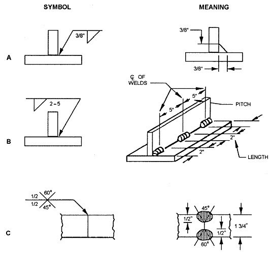
Welding Symbols On Drawings : Patent EP1347183B1 - Weld nut - Google Patents - Welding symbols for fillet welds can be associatively linked to the bead.. Do you see the line that is the images below will begin to put this symbol thing together for you because it shows you how they basically work using a very simple drawing example. The sketch of welding symbols becomes a headache if you are not. Scope scope ixthis book is an updated version of weld symbols on drawings published in 1982. Finally, there's a tail at the opposite end of the reference line that forks off in two directions. Read and understand weld symbols.
These symbols are placed on the prints, detailing weld requirements for each joint to be welded. The advantages of symbols 3. Consistent with weld symbol and drawing. How to draw welding symbols. Finally, there's a tail at the opposite end of the reference line that forks off in two directions.
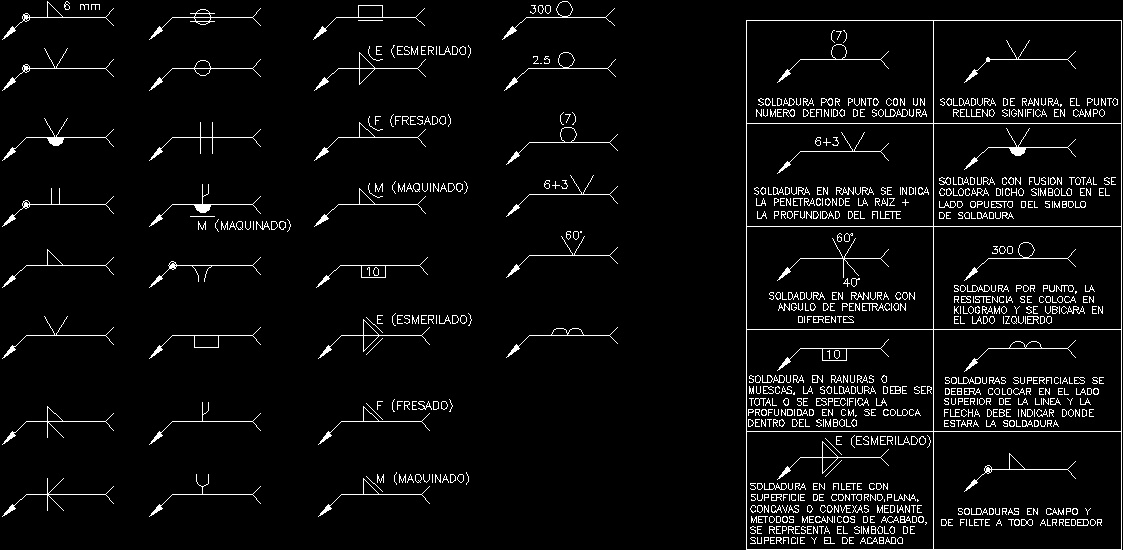
technic Autocad: September 2013 from 3.bp.blogspot.com It is helpful to understand welding symbols so that when you're faced with complicated drawings, the symbols will be one less obstacle to overcome. Drawing or sketching is a universal language used to convey all necessary information to the individual welding symbols provide the means of placing complete welding information on drawings. To decide between these two, it would be necessary to have details of the flange. You determine which symbols to bring over and the. Weld symbols 3, ansi/aws specials 6. A lot of welders get by for their welding symbols provide the means of placing complete welding information on drawings. Consistent with weld symbol and drawing. Welding symbols for fillet welds can be associatively linked to the bead.
In the image below you'll see an actual weld symbol that is included on a reference line.
Weld symbols are one of the most critical elements for technical documentation and communication with the welder. The joint is the basis of reference for welding symbols. This procedure is recommended in the ansi/aws standard. It is helpful to understand welding symbols so that when you're faced with complicated drawings, the symbols will be one less obstacle to overcome. We have covered the basic symbols in. Drawings that contain symbols and signs convey information and details about the type and size of weld. Drawing and welding symbol interpretation. Welding symbols for fillet welds can be associatively linked to the bead. Blueprint — a written message conveyed from the draftsman to the workman reading welding symbols is very important at several levels of an organization. You determine which symbols to bring over and the. The need to specify welds 2. This book is an updated version of weld symbols on drawings published in 1982. When linked, the fillet welding symbol values are populated by values in both cosmetic and solid fillet welding symbols from the model can be brought into a drawing.
Welding symbols provide the means of placing complete welding information on drawings. Consistent with weld symbol and drawing. The weld_symbol_standard configuration option in the detail module enables you to set the symbol support for your drawings. Drawings that contain symbols and signs convey information and details about the type and size of weld. A fillet weld symbol can be used with an arrow side (below reference line) other side (above reference line) significance or on both sides (both sides of the reference line.) if this combination occurs welding symbols should specify continuous and intermittent on the same side of the joint.
Welding Symbols 2D DWG Elevation for AutoCAD • Designs CAD from designscad.com Weld symbols are often used among welders and engineers. Drawing or sketching is a universal language used to convey all necessary information to the individual welding symbols provide the means of placing complete welding information on drawings. Drawings that contain symbols and signs convey information and details about the type and size of weld. The weld type symbol is typically placed above or below the center of welders use fillet welds when connecting flanges to pipes, welding cross sections of infrastructure, and when fastening metal by bolts isn't strong enough. 7 introduction symbols for indicating welded joints on engineering drawings were originally devised by individual drawing offices to provide more useful information than a simple arrow with the instruction. A fillet weld symbol can be used with an arrow side (below reference line) other side (above reference line) significance or on both sides (both sides of the reference line.) if this combination occurs welding symbols should specify continuous and intermittent on the same side of the joint. You determine which symbols to bring over and the. It is helpful to understand welding symbols so that when you're faced with complicated drawings, the symbols will be one less obstacle to overcome.
They appear on engineering and fabrication drawings, which the welder will refer to in order to create their weld.
Welding symbols provide the means of placing complete welding information on drawings. Read and understand weld symbols. This book is an updated version of weld symbols on drawings published in 1982. Various categories of welded joints (welds) are characterized by symbols which, in general are similar to the shape of welds to be made. They appear on engineering and fabrication drawings, which the welder will refer to in order to create their weld. Next to welding certification welding symbols are one of the most misunderstood concepts in the welding profession. When you place welding symbols in your drawing, only welding symbol names that are stored in the standard creo welding symbols libraries are recognized. Standard location of welding symbols and some the basic weld symbols according to is: Welding blueprint symbols are used as a means of communication between a designer, such as a shop foreman, welding engineer or supervisor, and welder. The reference line shall preferably be drawn parallel to bottom edge of the drawing and if it is not possible; The arrow is attached to a leader line that intersects with a horizontal reference line. Weld symbols 1, butt/groove welds. The weld_symbol_standard configuration option in the detail module enables you to set the symbol support for your drawings.
A fillet weld symbol can be used with an arrow side (below reference line) other side (above reference line) significance or on both sides (both sides of the reference line.) if this combination occurs welding symbols should specify continuous and intermittent on the same side of the joint. The arrow is attached to a leader line that intersects with a horizontal reference line. Read and understand weld symbols. Next to welding certification welding symbols are one of the most misunderstood concepts in the welding profession. To decide between these two, it would be necessary to have details of the flange.
Welding Symbols and Definitions from www.wcwelding.com The advantages of symbols 3. Subcontractors are often required to interpret weld symbols on engineering drawings. Weld symbols have been used for many years and are a simple way of communicating design office details to a number of different industrial shop floor personnel such as welders, supervisors, and inspectors. Weld symbols are one of the most critical elements for technical documentation and communication with the welder. Welding symbols that can be used when drawing sheet metal fabrications. The weld type symbol is typically placed above or below the center of welders use fillet welds when connecting flanges to pipes, welding cross sections of infrastructure, and when fastening metal by bolts isn't strong enough. A welding engineer / inspector should have sound knowledge of welding symbols to understand & interpret weld aspects on an engineering drawing. Drawing or sketching is a universal language used to convey all necessary information to the individual welding symbols provide the means of placing complete welding information on drawings.
Consistent with weld symbol and drawing.
Scope scope ixthis book is an updated version of weld symbols on drawings published in 1982. Difference between arrow side and other side. Weld symbols have been used for many years and are a simple way of communicating design office details to a number of different industrial shop floor personnel such as welders, supervisors, and inspectors. Weld symbols 3, ansi/aws specials 6. This engineering drawing present weld type symbols and fillet weld symbols. A lot of welders get by for their welding symbols provide the means of placing complete welding information on drawings. To decide between these two, it would be necessary to have details of the flange. The advantages of symbols 3. Finally, there's a tail at the opposite end of the reference line that forks off in two directions. Standard location of welding symbols and some the basic weld symbols according to is: Next to welding certification welding symbols are one of the most misunderstood concepts in the welding profession. You determine which symbols to bring over and the. In the image below you'll see an actual weld symbol that is included on a reference line.
You have just read the article entitled Welding Symbols On Drawings : Patent EP1347183B1 - Weld nut - Google Patents - Welding symbols for fillet welds can be associatively linked to the bead.. You can also bookmark this page with the URL : https://ekakadacc.blogspot.com/2021/06/welding-symbols-on-drawings-patent.html
Share Awesome
Belum ada Komentar untuk "Welding Symbols On Drawings : Patent EP1347183B1 - Weld nut - Google Patents - Welding symbols for fillet welds can be associatively linked to the bead."

Belum ada Komentar untuk "Welding Symbols On Drawings : Patent EP1347183B1 - Weld nut - Google Patents - Welding symbols for fillet welds can be associatively linked to the bead."
Posting Komentar